A Potential Solution to Assess the Absorbed Dose at Any Point in Breast During Digital Breast Tomosynthesis (DBT) Imaging Using a Novel Monte Carlo Simulation Software
A B S T R A C T
Estimating the average glandular dose (AGD) from a mammographic exam is essential for assessing radiation-induced cancer risk. In this study, we propose Mdec-Toki Monte Carlo Method with the aim of visualizing the dose distribution of the entire breast under different arbitrary glandularities, compressed thicknesses, and exposure parameters and evaluating the absorbed dose at an arbitrary point. A phantom with 50% glandularity values was used for the optically stimulated luminescence (OSL) dosimeters measurements to obtain the percentage depth dose PDD from the incident surface to the emission surface. Using the Mdec-Toki method under the same settings as those used for actual measurements and PDD was used to calculate the AGD. The PDD and AGD at an arbitrary point, obtained from Mdec-Toki method simulations and the actual measurements using OSL were similar. The proposed method may be adapted to individual patients and can support radiation safety management during mammography.
Keywords
Monte Carlo simulation, average glandular dose, mammography, tomosynthesis, percentage depth dose
Introduction
Mammograms are routine examinations for women aged 40 and above which require radiological protection to avoid undesired consequences [1, 2]. For instance, most breast cancers caused by radiation exposure originate in mammary gland tissue; this type of tissue has high radiosensitivity toward ionizing radiation and is susceptible to the development of radiation-induced breast cancer [3, 4]. Therefore, the exposure dose in mammography should not be evaluated by considering the incident surface dose, which is an exposure dose index for general X-ray imaging. Instead, it should be evaluated by considering the average glandular dose (AGD), which corresponds to the radiation absorbed by mammary tissue, including the subcutaneous stromal tissue (predominantly adipose tissue) [5, 6]. Currently, the method proposed by Dance et al. and used by the European Reference Organisation for Quality Assured Breast Screening and Diagnostic Services (EUREF) has also been adopted by Japan to obtain the AGD during mammography [7-9].
The Dance method calculates the AGD by multiplying the factor related to the half-value layer, target/filter combination of the incident X-ray flux, and the factor corresponding to 50% glandularity with poly (methyl methacrylate; PMMA) phantoms, with thickness (i.e., equivalent compressed breast thickness) given as a parameter. For digital breast tomosynthesis (DBT), factors related to the scanning angle of the X-ray tube and the air kerma measured on its incident surface are multiplied by the abovementioned factors to determine the AGD [10]. As evaluating the exposure dose of individual mammography patients is extremely complicated, conducting quality control with the AGD obtained from a standard phantom leads to the development of measures to reduce the exposure dose of a patient [11]. However, the radiation absorption of the mammary gland changes with respect to the depth and cannot be determined by using the AGD alone. In addition, the absorbed dose at an arbitrary point in the breast cannot be evaluated [12]. Although the increase in incidences of breast cancer caused by mammography examinations has not been directly investigated, analyses using various models have determined significant carcinogenic risks resulting from mammography [13-16]. Thus, the radiation absorbed by mammary gland tissue should be determined for dose management to estimate the carcinogenic risk.
This study aimed to provide an accurate and effective method to determine the percentage depth dose (PDD) and average glandular dose during DBT at any point in the mammary gland. The proposed method of Mdec-Toki, based on Monte Carlo simulations, considers factors such as glandularity, tissue thickness and structure, heel effects, and the mammography imaging conditions to provide accurate estimates that show suitable agreement with measurements. The depth absorbed dose was measured during DBT of breast phantoms with a glandularity value of 50% using an optically stimulated luminescence dosimeter (OSLD). The PDD and the dose distribution map were calculated from the measurements. The dose distribution map was created on the plane parallel to the detector at each depth, and the absorbed dose at any point was evaluated. PDD in mammo with Monte Carlo has been used long before [17]. Additionally, the three-dimensional dose distribution during DBT under the same settings as those used for actual measurements was calculated and compared using the Original Monte Carlo simulation method, Mdec-Toki.
Materials and Methods
I Depth Absorbed Dose Measurements using OSLD and Creation of Dose Distribution Map
Poly (methyl methacrylate; PMMA) phantom (Fujifilm Medical, Tokyo, Japan) was used for the measurements in this study. Three types of phantom dimensions, including a rectangular cross-section of 24×30 cm and thicknesses of 5, 10, and 20 mm, were used in combination. The AMULET Innovality system (Fujifilm Medical, Tokyo, Japan) was used for breast X-ray imaging (Figure 1A). In addition, a nanoDot dosimeter (Landauer Inc., Glenwood, IL, USA) was used as the OSLD, and a microSTAR ii dosimetry system (Landauer Inc., Glenwood, IL, USA) was used as the reader. Traceability was ensured for the measured data with an ion chamber dosimeter (Model 9015, 10×5-6M ion chamber; Radcal, Monrovia, CA, USA). The following imaging settings were considered: tube voltages of 24, 29, 34, 39, and 44 kV, a tube current-time product of 80 mAs, W/Al target/filter, and high-resolution mode with a scanning angle of ±20° [18]. The OSLDs were placed at 130 locations relative to the craniocaudal view (Figure 1B).

Figure 1: A) A lateral view of the absorbed dose measurement geometry using OSLD (a-focus, b- phantom surface with OSLD dosimeters, c- receptor). B) Geometry of OSLD dosimeters placement during the absorbed dose measurement.
The phantom surface was set as the origin (0 mm), and the absorbed dose per depth for the 60 mm phantom thickness was measured at 5-mm intervals, and the PDD was calculated at a position 6 cm from the chest wall edge (set as the evaluation point during DBT accuracy control). By analysing the absorbed dose of the entire phantom, the PDD was calculated, and the dose distribution map was created. The phantom was placed at the center of the left and right sides of a breast support table such that it was aligned with the chest wall edge of the table. In addition, the compression plate was placed in contact with the upper surface of the phantom. Measurements were performed three times per depth.
II PDD, Three-Dimensional Dose Distribution, and AGD Calculation Using Mdec-Toki Method Based on Monte Carlo Simulation
Original code was written in Microsoft Visual Basic 6 and Fortran 77 to perform the simulations in this study. A graphical user interface was created to input parameters and settings for the phantom. Figure 2 shows the irradiation geometry for the proposed Mdec-Toki method based on Monte Carlo simulations. The source-to-image distance was set to 65 cm, and the compression plate was made of 1.5 mm polycarbonate. For mammography, the X-ray tube was fixed, and for DBT, the X-ray tube was rotated from -20° to 20° with respect to the patient.
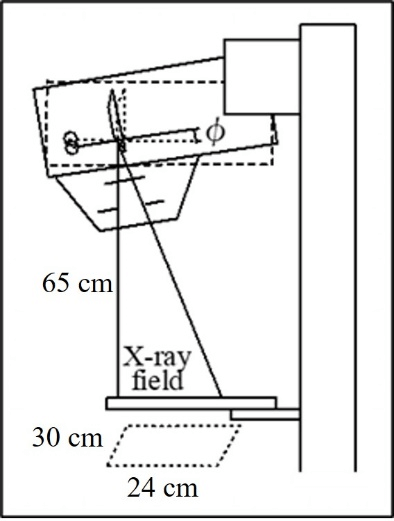
Figure 2: Irradiation geometry of phantom for Mdec-Toki method based on Monte Carlo simulations (a-cathode, b-anode, c-filter, d-collimator).
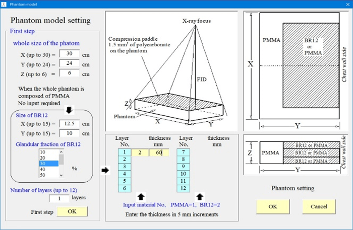
Figure 3: Phantom setting interface for Mdec-Toki method.
Figure 3 shows the phantom setting screen. The phantoms had cross-sections of 30×24cm and varying thicknesses. Either the PMMA or the breast equivalent phantom can be selected. A breast-equivalent homogeneous phantom corresponding to a mammary gland ratio of 0 to 100% can be selected and the thickness set. The composition and density of each phantom according to their mammary gland ratio are shown in (Table 1). It was used the same breast-equivalent phantom as Boone [19].
Table 1: The composition and density of each mammary gland ratio of the phantom according to the mammary gland ratio.
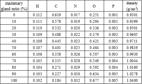
Figure 4 shows an example calculation screen for the incident X-ray spectrum. The following conditions were considered: tungsten as the target material, target angle of 16°, and X-ray beam inclination angle of 6°. In addition, the tube voltage, tube current-time product, additional filter, and other parameters were adjusted during the actual measurements. The spectrum shown in (Figure 4) is located closest to the patient’s chest wall.
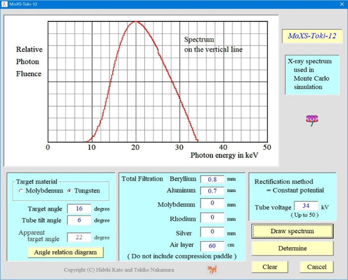
Figure 4: Calculation interface for the incident X-ray spectrum.
Thus, the X-ray spectrum was calculated at 0.5° radiation angle intervals after considering the heel effect and then used for the simulations. To approximate the spectrum, the equation proposed by Tucker et al. was used for the tungsten target, and that proposed by Kato et al. was used for the molybdenum target [20, 21]. Next, the imaging method was selected (Mammography or DBT). In the case of DBT, the tube runout angle was set. Based on these settings, in the Monte Carlo simulation code, the cross-section of the interaction between photons and each phantom material is based on the data of Berger et al., and the shape factors and incoherent scattering functions are based on the data of Hubbell et al., based on the weight ratio of the constituent elements [22, 23]. The value calculated by the addition rule is used [24]. Ehrhardt’s method is used to generate pseudo-random numbers. The number of incident photon histories was 1000000000 [25].
The interior of the phantom and the air kerma at the surface position where the radiation was incident on the subject were divided into voxels with 1-mm sides, and the energy absorbed in each voxel was converted into the absorbed dose. The three-dimensional dose distribution was determined to calculate the PDD at the center of the phantom. This 100% dose was the relative dose at an absorbed dose of 1 mGy on the surface of the PMMA phantom. Hence, the absorbed dose at each depth of an arbitrary phantom could be easily calculated from the absorbed dose measured on the surface of the PMMA phantom under irradiation conditions. The average PDD and AGD at each depth from the incident surface to the emission surface were calculated using this relation. PDD values are given at 1 mm intervals in the depth direction. The average PDD value (PDD average) from the entrance surface to the ejection surface can be calculated using the following equation, assuming that the phantom thickness is N mm.
\[{PDD}_{average}=\frac{1}{N}\sum_{i=1}^{N}{PDD(i)}\]Where PDD (i) is the PDD value at a depth of i mm. As mentioned above, the absorbed dose corresponding to PDD = 100% is a value normalized by the incident surface dose (PMMA absorbed dose) when the phantom is PMMA. The AGD is calculated by multiplying by the PDD average as follows:
\[AGD=D_{surface,PMMA}\times{PDD}_{average}/100\]III AGD Calculation Using Dance Method
The AGD was calculated at the time of DBT imaging using the Dance method published in 2013 [26]. A semiconductor dosimeter (Piranha, RTI Electronics, Mölndal, Sweden) was used, and traceability was ensured for the measured data with the ion chamber dosimeter. The following imaging settings were considered: tube voltage of 34 kV, tube current-time product of 80 mAs, W/Al target/filter, and high-resolution mode with a scanning angle of ±0°. This incident air kerma was used to determine the value at a phantom thickness of 60 mm.
Results
I Depth Absorbed Dose Measurements Using OSLD and Dose Distribution Map
Figure 5A shows the PDD curves obtained using the OSLD during DBT imaging. The absorbed dose at 0 mm corresponded to 100% in the graph. The dotted and solid lines represent the measurements and PDD approximated by an exponential function, respectively. Figure 5B shows the dose distribution chart at each depth.
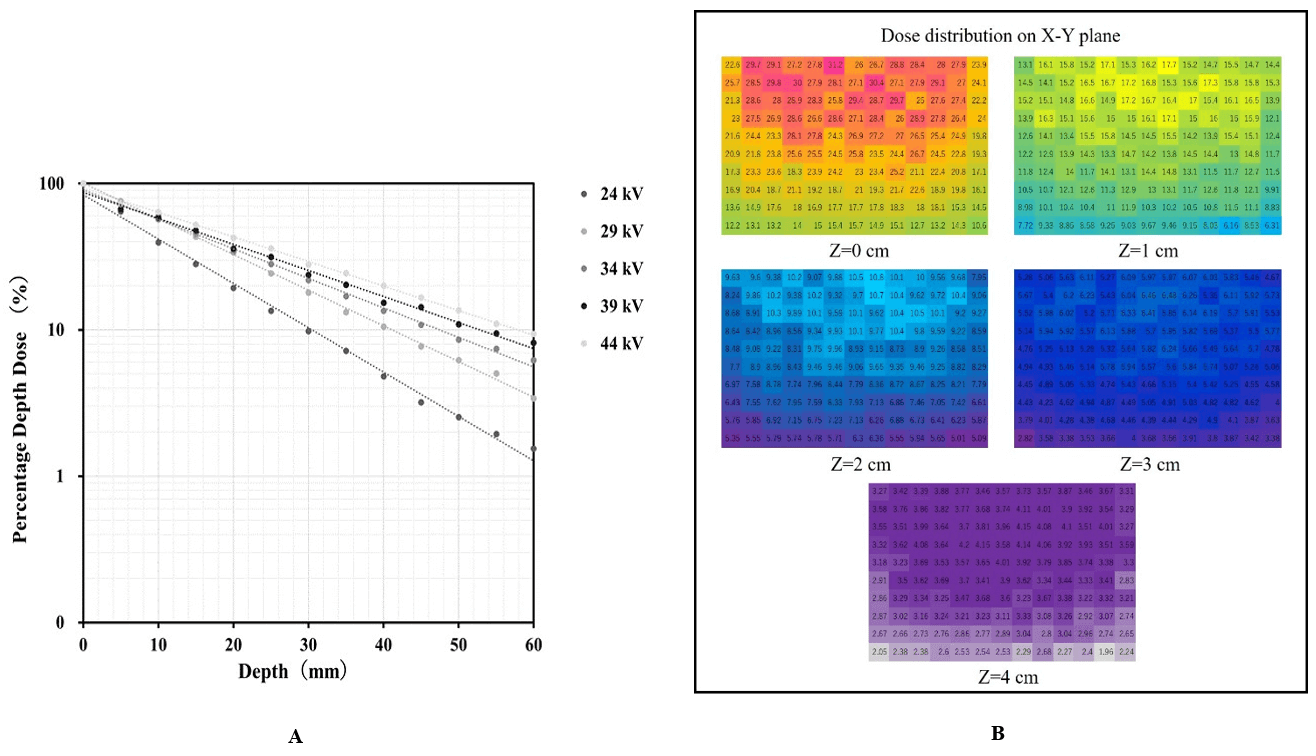
Figure 5: A) PDD curves obtained using OSLD. B) Dose distribution chart at each depth.
II PDD, Three-Dimensional Dose Distribution, and AGD Calculation Using Mdec-Toki Method Based on Monte Carlo Simulation
Figure 6A shows the PDD curves obtained using the proposed Mdec-Toki method during DBT imaging. Figure 6B shows the three-dimensional dose distribution chart at each depth. The absorbed dose of the voxel at a depth of 0-1 mm corresponds to 100% in the graph. A build-down phenomenon can be observed near the emission surface because of the decrease in the number of backscattered rays. The AGD was simulated at the time of DBT imaging by Mdec-Toki method. Its value was obtained as 3.89 mGy.
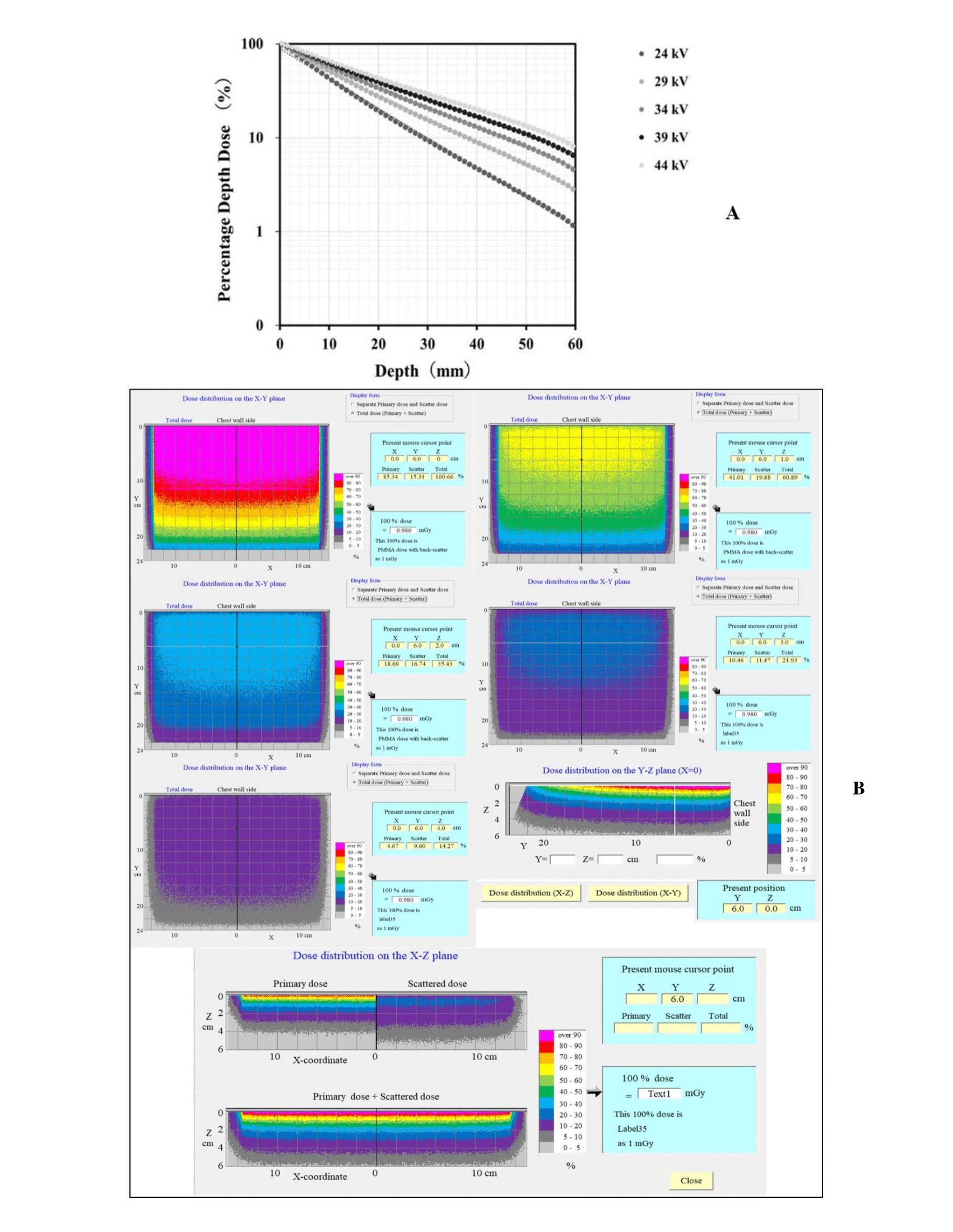
Figure 6: A) PDD curves obtained using Mdec-Toki method. B) Three-dimensional dose distribution using Mdec-Toki method.
III AGD Calculation Using Dance Method
The AGD is given by D = K∙g∙s∙c∙t. AGD D was determined by multiplying the incident air kerma by factor g for breast tissue with 50% glandularity at the PMMA thickness (equivalent compressed breast thickness) given by the half-value layer, factor s related to the target/filter combination, factor c, which corrects for breast compositions differing from 50% glandularity, and factor t for an X-ray tube scanning angle of ±20°. Conversion factors g, s, and t were calculated considering the protocol for the Quality Control of the Physical and Technical Aspects of Digital Breast Tomosynthesis Systems version 1.03 and using interpolation. Its value was obtained as 3.74 mGy.
Discussion
Some previous studies have estimated the depth dose and glandular dose by using a digital mammography unit [12, 27]. Determining the dose at arbitrary depths from the PDD is essential, given the higher sensitivity of the mammary gland tissue to radiation-induced cancers than the skin on the breast (tissue weighting factor: 0.12). The X-ray beams used for mammography have low energy, and the depth dose decreases sharply as the depth increases [20]. The distribution of mammary glands in the breast is not uniform and changes with age, mammary gland tissue, and adipose tissue, which is distributed under subcutaneous fat. In addition, the stochastic effects (carcinogenesis) of the breast alone should be considered, given the extremely specific imaging site [28]. Many countries have adopted a method to evaluate the AGD from air dose (air kerma) following a conventional approach for DBT dose evaluation during mammography. This adoption may be due to the difficulty in evaluating the depth dose under low incident photon energy during breast examinations. The present study develops a novel experimental dose estimation method in the irradiation field of the DBT. Figures 5A & 6A evidenced that the PDDs obtained from the measurements were almost identical to those obtained from the simulations.
Despite its small size, the OSLD provides suitable characteristics, such as tissue equivalence, high sensitivity, and reusability, which are important for dose measurements, including those of scattered radiation in diagnostic imaging [29-35]. McKeever et al. reported that the OSLD could measure extremely small doses, on the order of 10 μGy [36]. According to the study by Kawaguchi et al., the uncertainty of OSL measurement was 5% or less for the uniformity of the nanoDot dosimeter, 2% or less for the incident side, and 4% or less for the ejection side [37]. It is known that the linearity is 5% or less (2% or less for 1 mGy or more), the energy dependence is about 10% on the incident side, and the difference between the incident side and the emission side is 6-8%. The angle dependence is 4% or less when the X-rays are incident on the detection surface of the nanoDot dosimeter within ± 30° from the vertical direction. In addition, since the measurement in the phantom has a large error owing to energy dependence, it should be calibrated using the effective energy of the measurement position. Later, by using X-rays vertically incident on the detection surface of the nanoDot dosimeter, an error of about 5% was obtained, and it was considered to be a useful small dosimeter for mammography dosimetry.

Figure 7: Results of PDD and AGD obtained from Mdec-Toki method.
Thus, depth dose measurements using the OSLD in DBT are useful, as demonstrated in this study. The dose distribution at each depth was obtained in three dimensions by Mdec-Toki. It almost matched the distribution that was obtained by actual measurements using OSLD and could grasp the dose at any point in the breast. The proposed Mdec-Toki simulation method to calculate the PDD and AGD considers the heel effects specific to mammography. Few glandular dose evaluation methods have used this type of Monte Carlo simulation. Figures 3 & 4 show that Mdec-Toki selects the glandularity of the phantom and calculates the incident X-ray spectrum using an approximate equation, enabling the determination of the absorbed dose, PDD curve, and AGD in each voxel of a phantom using Monte Carlo simulations (Figure 7). The AGD comparisons showed that the PDD curves obtained by simulations and the Dance method differed by 4.0%. These variations reflect differences in the composition, density, and photon interaction cross-section of reference PMMA phantom and breast-equivalent phantom that is used in the Dance method and simulations, respectively, as well as the accuracy of the incident X-ray spectrum (i.e., error with respect to the actual X-ray spectrum). However, considering the uncertainty in the actual measurements, this error is considered to be within experimental uncertainty.
Conclusion
The results obtained from Mdec-Toki provide basic data for managing the radiation safety of patients, and it is possible to visualize the dose distribution of mammography. The PDD in a breast-equivalent phantom calculated using the proposed Mdec-Toki method based on Monte Carlo simulations suitably agrees with the PDD measured using an OSLD. Furthermore, the AGDs calculated using the PDD and the Dance method were similar. Therefore, the proposed Mdec-Toki method can be used to estimate and evaluate the absorbed dose under different arbitrary breast locations, glandularity values, tissue thicknesses, and imaging conditions. However, the absorbed dose varies because of individual differences in imaging conditions and the structure of the breast. Therefore, the content of mammary gland tissue and the subcutaneous fat layer in the breast should be considered to establish a phantom that resembles the actual structure. Moreover, simulations and optimization of the imaging conditions should be conducted by varying factors such as the tube voltage and target filter. The Mdec-Toki method will be further improved and used to determine exposure doses in actual patients undergoing mammography. The proposed method may be adapted to individual patients and can support radiation safety management during mammography.
Article Info
Article Type
Research ArticlePublication history
Received: Wed 09, Feb 2022Accepted: Thu 24, Feb 2022
Published: Fri 11, Mar 2022
Copyright
© 2023 Tokiko Nakamura. This is an open-access article distributed under the terms of the Creative Commons Attribution License, which permits unrestricted use, distribution, and reproduction in any medium, provided the original author and source are credited. Hosting by Science Repository.DOI: 10.31487/j.RDI.2022.01.01
Figures & Tables
Table 1: The composition and density of each mammary gland ratio of the phantom according to the mammary gland ratio.
References
1. Ministry of Health,
Labour and Welfare; Health, Medical Care.
2. European Society of Radiology (ESR), European Federation of
Radiographer Societies (EFRS) (2019) Patient Safety in Medical Imaging: a joint
paper of the European Society of Radiology (ESR) and the European Federation of
Radiographer Societies (EFRS). Insights Imaging 10: 45. [Crossref]
3. Yaffe MJ, Mainprize
JG (2011) Risk of radiation-induced breast cancer from mammographic screening. Radiology 258: 98-105. [Crossref]
4. Gennaro G, Bernardi
D, Houssami N (2018) Radiation dose with digital breast tomosynthesis compared
to digital mammography: per-view analysis. Eur
Radiol 28: 573-581. [Crossref]
5. Lekatou A, Metaxas
V, Messaris G, Antzele P, Tzavellas G et al. (2019) INSTITUTIONAL BREAST DOSES
IN DIGITAL MAMMOGRAPHY. Radiat Prot
Dosimetry 185: 239-251. [Crossref]
6. Barzanje SLH, Harki
EMTN (2017) Estimation of mean glandular dose for patients who undergo
mammography and studying the factor affecting it. AIP Conf Proc 1888: 020020.
7. Dance DR (1990)
Monte Carlo calculation of conversion factors for the estimation of mean
glandular breast dose. Phys Med Biol
35: 1211-1219. [Crossref]
8. Dance DR, Skinner
CL, Young KC, Beckett JR, Kotre CJ (2000) Additional factors for the estimation
of mean glandular breast dose using the UK mammography dosimetry protocol. Phys Med Biol 45: 3225-3240. [Crossref]
9. European Reference
Organization for Quality Assured Breast Screening and Diagnostic Services
(2018) Protocol for the Quality Control of the Physical and Technical Aspects
of Digital Breast Tomosynthesis Systems.
10. Dance DR, Young KC,
van Engen RE (2011) Estimation of mean glandular dose for breast tomosynthesis:
factors for use with the UK, European and IAEA breast dosimetry protocols. Phys Med Biol 56: 453-471. [Crossref]
11. Hammerstein GR,
Miller DW, White DR, Masterson ME, Woodard HQ et al. (1979) Absorbed radiation dose
in mammography. Radiology 130: 485-491. [Crossref]
12. Tsai HY, Chong NS,
Ho YJ, Tyan YS (2010) Evaluation of depth dose and glandular dose for digital
mammography. Radia Meas 45: 726-728.
13. Awai K (1999)
Radiation exposure and protection in angiography. Japan Soc Radiol Technol 17:
22-25.
14. Togashi A (2001)
Considering radiation protection from the report on dermatopathy by IVR. Japan Soc Radiol Technol 57: 1444-1450.
15. Eguchi Y, Kimura H,
Tosa T (1998) Approach for dose reduction. Toho
Jyun Satsu Kenk 34-36.
16. Iumura T, Matsumoto
T, Tateno Y (1989) Risk-benefit
analysis for mass screening of breast cancer utilizing mammography as a
screening test. Niho Igaku Hosh Gakk Zass 49: 1091-1095.
17. Metaxas V, Delis H, Kalogeropoulou C, Zampakis P (2005) Contrast to Noise Ratio and Contrast
Detail Analysis in Mammography: A Monte Carlo Study. J Phys Conf Ser 637: 012017.
18. Fukuda W, Morita J,
Yamada M (2016) Improved tomosynthesis reconstruction using super-resolution
and iterative techniques. FujiF Res Dev 61:
1-7.
19. Boone JM (1999) Glandular
breast dose for monoenergetic and high-energy X-ray beams: Monte Carlo
assessment. Radiology 213: 23-37. [Crossref]
20. Tucker DM, Barnes
GT, Chakraborty DP (1991) Semiempirical model for generating tungsten target
x-ray spectra. Med Phys 18: 211-218.
[Crossref]
21. Kato H, Fujii S,
Shirakawa S, Suzuki Y, Nishii Y (2011) [A presumption calculating formula of
the X-ray spectrum generated from a molybdenum target X-ray tube]. Nihon Hoshasen Gijutsu Gakkai Zasshi 67: 193-201. [Crossref]
22. Berger MJ, Hubbell
JH, Seltzer SM, Chang J, Coursey JS et al. (1998) XCOM: Photon Cross
Sections Database (NBSIR 87-3597). Nati Inst Stand Techn.
23. Hubbell JH, Veigle
WJ, Briggs EA, Brown RT, Cromer DT et al. (1975) Atomic form factors,
incoherent scattering functions, and photon cross sections. J Phys Chem Ref
Data 4: 471-538.
24. Hubbell JH (1969)
Photon Cross Sections, Attenuation Coefficients, and Energy Absorption
Coefficients From 10 keV to 100 GeV (NSRDS-NBS 29). Nati
Bure Stand 29: 85.
25. Ehrhardt JC (1986)
Generation of pseudorandom numbers. Med Phys 13: 240-241. [Crossref]
26. Amendoeira I, Perry
N, Broeders M, de Wolf C, Törnberg S et al. (2013) S1 Digital mammography
update European guidelines for quality assurance in breast cancer screening and
diagnosis 2013 Fourth edition. Luxem Supp Euro Commi Offi Offic Publi Euro
Comm 1-60.
27. Souza LF, Gomes DS,
Squair PL, Souza DN, Nogueira MS (2020) Experimental dose estimation in
anthropomorphic breast phantom in clinical mammography systems. Fift Int Wor Brea Imag.
28. Maekoshi H, Kimura
C, Koyama S, Sakamoto H, Sunayashiki T et al. (1997) Nationwide investigation
for standardization of exposure measurement accuracy of soft X-rays used by
mammography. Japan Soc Radiol Technol 55:
394-397.
29. Katoh T, Matsumoto
M, Higashida Y (1999) Nationwide survey of glandular tissue dose for
establishment of breast cancer screening using mammography. J Japan Assoc
Breast Cancer Screen 8:
165-173.
30. Zhang S, Peng H, He
L, Zhang X, Gao Y et al. (2017) Response of Fingernail Growth to Out-Of-Field
Low-Dose X ray in Cancer Patients Receiving Radiotherapy. Radiat Res 187: 682-688. [Crossref]
31. McKeever SWS (2011)
Optically stimulated luminescence: A brief overview. Radiat Meas 46: 1336-1341.
32. Suzuki A, Ito M
(2001) Characteristics of OSL dosimeters. Japan Atom Ener Res Insti.
33. Suzuki A, Suzuki T,
Takahashi M, Nakata T, Murayama T et al. (2015) Characteristics of OSL
dosimeter for individual monitoring for external radiation. JAEA Technol.
34. Perks CA, Roy GL,
Prugnaud B (2007) Introduction of the InLight monitoring service. Radiat Prot Dosim 125: 220-223. [Crossref]
35. Al Senan RM, Hatab
MR (2011) Characteristics of an OSLD in the diagnostic energy range. Med Phys 38: 4396-4405. [Crossref]
36. McKeever SWS, Akselrod MS, Markey BG (1996) Pulsed optically Stimulated Luminescence Dosimetry Using Alpha‐Al2O3: C. Radiat Prot Dosim 65: 267-272.
37. Kawaguchi A, Matsunaga Y, Suzuki S, Chida K (2016) Energy dependence and angular dependence of an optically stimulated luminescence dosimeter in the mammography energy range. J Appl Clin Med Phys 18: 191-196. [Crossref]